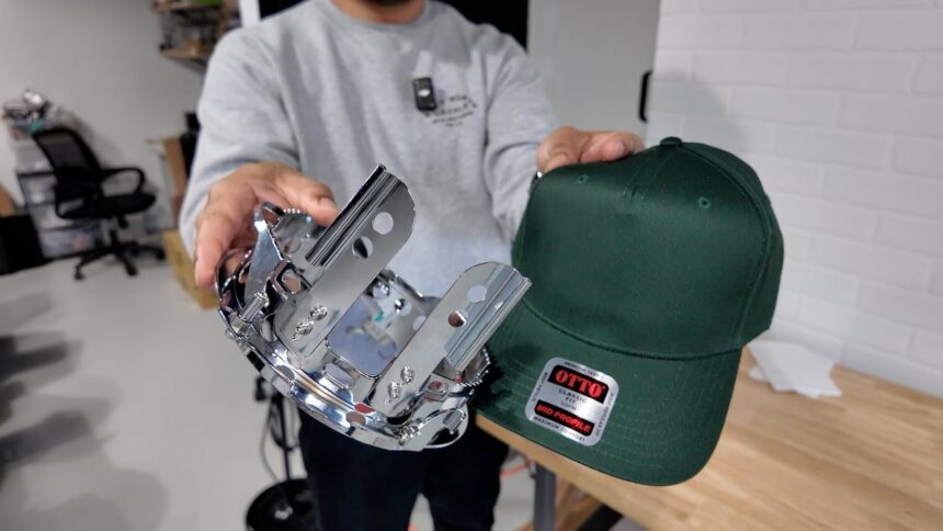
Introduction to Smart Stitch 1201 Hat Driver Diagrams
In the dynamic world of embroidery and sewing machines, the integration of advanced drivers and control modules has revolutionized how operators manage their equipment. One such pivotal component is the Smart Stitch 1201 Hat Driver diagrams, a sophisticated device designed to enhance embroidery precision, streamline operations, and improve overall productivity. To understand its functionality and optimize its use, it’s essential to delve into the diagrams that illustrate its architecture, wiring, and operational flow. This article provides an in-depth exploration of the Smart Stitch 1201 Hat Driver diagrams, explaining their significance, components, and practical applications.
Understanding the Smart Stitch 1201 Hat Driver diagrams
Before examining the diagrams, it’s crucial to grasp what the Smart Stitch 1201 Hat Driver diagrams entails. It is a specialized driver module used primarily in embroidery machines to control the sewing head’s movements, needle operations, and stitch sequences. Its purpose is to translate digital commands into precise mechanical actions, ensuring high-quality embroidery results, especially for intricate designs like hats and caps.
The driver integrates various electronic components such as microcontrollers, motor controllers, sensors, and communication interfaces. It acts as the brain behind the embroidery machine, coordinating complex tasks seamlessly.
Importance of Driver Diagrams
Driver diagrams serve as visual schematics that map out the internal and external connections of the device. They provide technicians and engineers:
- Clarity: Clear visualization of component relationships.
- Troubleshooting: Easier identification of faults or wiring issues.
- Installation Guidance: Step-by-step wiring and connection instructions.
- Maintenance and Upgrades: Understanding the architecture for modifications.
For the Smart Stitch 1201 Hat Driver diagrams, detailed diagrams are invaluable given the device’s complexity and the precision required in embroidery applications.
Components Featured in the Diagrams
The typical Smart Stitch 1201 Hat Driver diagrams include various interconnected components:
- Power Supply Section:
- Converts external power sources into usable voltage levels.
- Includes voltage regulators, filters, and fuses.
- Microcontroller Unit (MCU):
- The core processing unit managing commands.
- Often based on ARM or AVR architecture.
- Motor Drivers:
- Control stepper motors responsible for head movement.
- Include drivers like the L298N or specialized stepper driver ICs.
- Sensor Connections:
- Limit switches, fabric sensors, and position encoders.
- Provide feedback to ensure accurate positioning.
- Communication Ports:
- USB, serial, or Ethernet interfaces.
- Facilitate data transfer from control software.
- Output Modules:
- Control signals for needle operation, thread tension, etc.
Typical Structure of the Smart Stitch 1201 Hat Driver Diagrams
The diagrams generally follow a layered architecture:
1. Power and Ground Layer
At the foundation, the diagrams depict the power input, including AC/DC converters, voltage regulators, and grounding points. Proper grounding is critical to prevent electrical noise and ensure safety.
2. Control Circuitry Layer
This layer shows the microcontroller, associated reset circuits, clock sources, and interfaces. It highlights how the MCU communicates with other modules via UART, SPI, or I2C protocols.
3. Motor Control Layer
A detailed section illustrating how stepper motor drivers connect to the microcontroller. It includes driver ICs, their input pins, power lines, and feedback sensors.
4. Feedback and Sensor Layer
This part maps limit switches, optical encoders, and other sensors that inform the driver about the machine’s position, enabling precise movements.
5. Output and User Interface
Diagrams often feature control buttons, indicator LEDs, and connection points for user input devices.
Reading and Interpreting the Smart Stitch 1201 Hat Driver diagrams
Understanding the diagrams requires familiarity with schematic symbols and conventions:
- Lines: Represent electrical connections.
- Symbols: Show components like resistors, capacitors, ICs, connectors.
- Labels: Indicate pin numbers, voltage levels, or signal names.
- Color Coding: Sometimes used to differentiate power, ground, signals, and control lines.
For example, a microcontroller pin connected to a motor driver input is typically shown as a line from the MCU symbol to the driver IC, with labels specifying the function (e.g., “STEP” or “DIR” for step and direction signals).
Practical Applications and Troubleshooting
Having access to the Smart Stitch 1201 Hat Driver diagrams enables technicians to:
- Diagnose Connectivity Issues: Verify wiring against the schematic.
- Replace Faulty Components: Identify which ICs or connectors are involved.
- Upgrade Systems: Add new sensors or communication modules based on existing architecture.
- Optimize Performance: Fine-tune motor control parameters by understanding the driver circuitry.
For instance, if the embroidery machine exhibits inconsistent stitching or motor jitter, inspecting the motor driver section per the diagram can reveal loose connections or faulty driver ICs.
Tips for Using the Diagrams Effectively
- Obtain the Correct Version: Manufacturer updates may alter schematics.
- Cross-Reference with the Manual: Use the diagram alongside technical manuals for clarity.
- Follow Safety Protocols: Always disconnect power before inspecting or modifying wiring.
- Use Proper Tools: Multimeters, oscilloscopes, and logic analyzers aid in verifying signals.
Conclusion
The Smart Stitch 1201 Hat Driver diagrams are essential resources for ensuring the reliable operation, maintenance, and upgrade of embroidery machines equipped with this driver module. They provide a detailed blueprint of the device’s electronic architecture, facilitating troubleshooting and technical improvements.
In the realm of high-precision embroidery, understanding these diagrams empowers technicians and engineers to maintain optimal machine performance, troubleshoot effectively, and implement enhancements confidently. As embroidery technology continues to evolve, such detailed schematics remain invaluable for ensuring machines operate seamlessly, producing beautiful, intricate designs with efficiency and consistency.
Note: For actual diagrams, wiring schematics, or specific technical drawings related to the Smart Stitch 1201 Hat Driver diagrams , consult the manufacturer’s official documentation or authorized technical support.


